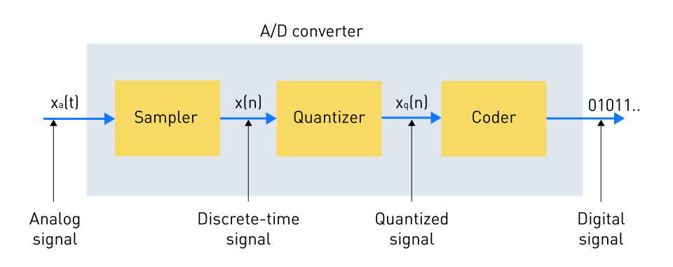

Figure 3: Basic components of an analog-to-digital converter
A foundational idea in information theory and signal processing is the Nyquist-Shannon Sampling Theorem, sometimes known as the Nyquist Theorem. It establishes a crucial correlation between the sampling frequency of a signal and its bandwidth, laying the foundation for the transformation of continuous analog signals into discrete digital signals.
According to the theory, if a continuous-time signal is band-limited and the sampling rate is at least twice the signal bandwidth (or, for baseband signals, twice the highest frequency component), the signal may be uniquely represented in its samples and retrieved back from them. This may be modeled mathematically as:
where Fs is the sampling frequency (or sampling rate), and Fmax is the highest frequency component present in the baseband signal.
This theorem is significant because it establishes the prerequisites for a flawless reproduction of the original analog signal from its samples. If the sampling theorem is broken, it is impossible to recover the original signal properly and information gets lost.
The Nyquist-Shannon Sampling Theorem is the source of the phrase "Nyquist Rate," which denotes the lowest rate at which a signal must be sampled in order to prevent information loss. The highest frequency component of the baseband signal is double what the Nyquist Rate is.
$$Nyquist Rate = 2 * F_$$
High-frequency components are reflected into lower frequencies when the sampling rate is lower than the Nyquist Rate, a process known as "aliasing," which results in distortion in the reconstructed signal.
It is crucial to remember that the Nyquist Rate is the very minimum sampling rate that may theoretically be used for flawless reconstruction. In order to accommodate for faults in the actual implementation of filters and other components, a slightly higher sample rate is sometimes utilized.

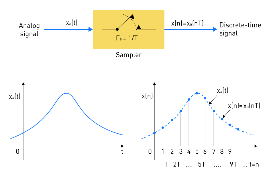
Figure 4: Periodic sampling of an analog signal
A continuous analog signal is first transformed into a discrete digital signal by sampling. The procedure entails periodic measurements or snapshots of the analog signal's amplitude at predetermined periods in time. The discrete set of data points that these pictures, or samples, reflect the original signal in the digital realm. The sample rate or sampling frequency is the frequency at which these photographs are taken.
In mathematical terms, if 'x(t)' is a continuous-time analog signal, the sampled signal 'x[n]' can be represented as:
where 'Ts' is the sampling period (the time interval between consecutive samples), 'n' is an integer, and 'x[n]' denotes the value of the signal at the nth sample.
In real life, sample and hold circuits are typically used to execute the sampling process. These circuits collect and hold the signal value for a brief period of time.
According to the Nyquist-Shannon sample Theorem, for an accurate representation of the baseband signal, the sample rate must be at least twice the highest frequency component. Aliasing happens when the sampling rate falls below this limit (the Nyquist Rate).
A phenomenon known as aliasing occurs when the signal's higher and lower frequency components cannot be distinguished from one another. In essence, higher frequencies are "folded" back into lower frequencies or "aliased" into them, which distorts or presents the original signal incorrectly. This occurs as a result of the samples' inability to accurately record the high-frequency components' quick changes at low sampling rates, which makes those changes seem as slower fluctuations.
It is standard procedure to apply an anti-aliasing filter prior to sampling in order to prevent aliasing. This low-pass filter removes or weakens the signal's high-frequency components that are above the Nyquist frequency.

Figure 5: Anti-aliasing filter
Quantization comes after sampling as a crucial step in converting continuous analog signals to digital signals. A continuous set of values (like voltage levels) is quantized into a discrete set of values. During the analog-to-digital conversion process, each sampled value is matched with the closest value among a limited number of discrete levels.
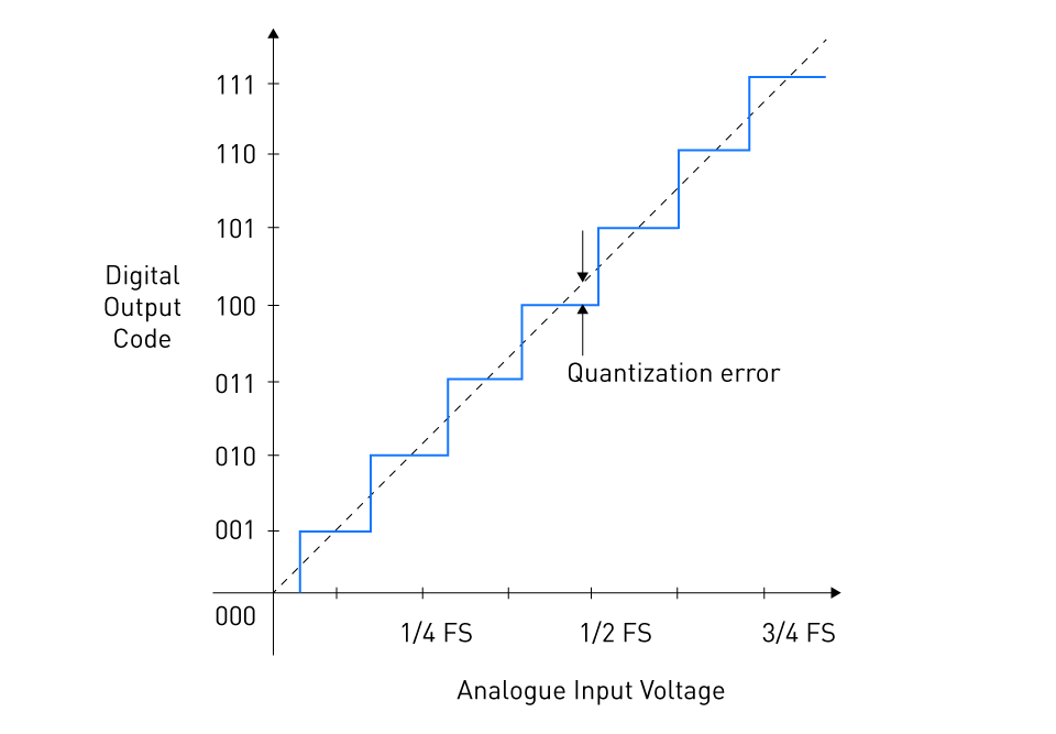
Consider the sampled signal's amplitude as a continuous range. This range is split into quantized fixed intervals, each of which corresponds to a distinct digital code or level. The quantity of these intervals, or quantization levels, is determined by the quantization resolution, expressed in bits. For example, there are 2^3 = 8 different levels to which the sampled values may be translated with a 3-bit quantizer.

Figure 6: Quantization error
Since quantization converts a continuous collection of values to a discrete set, it naturally involves an approximation inaccuracy. The discrepancy between the actual sampled value and the quantized value to which it is mapped is referred to as quantization error.
Since the nature of quantization error is largely unpredictable, it may be thought of as noise added to the signal. It can, however, be examined and its consequences recognized. The error is often constrained to ±(1/2) of the quantization step size, which is the separation between neighboring quantization levels.
As was already established, the resolution of the quantizer—typically measured in bits—determines the number of quantization levels. The number of quantization levels increases with resolution, while the quantization error decreases. There are 2^N quantization levels for an N-bit quantizer. An 8-bit quantizer, for instance, will have 2^8 = 256 levels.
The signal range divided by the quantity of quantization levels yields the quantization step size. For instance, the step size would be 10/256 ≈ 0.039 volts for a signal that ranges from 0 to 10 volts and has 256 quantization levels.
For high-fidelity applications, high-resolution quantization is preferred because it lowers quantization error. It also needs extra bits for representation, which might result in a trade-off in terms of bandwidth and storage.

ARTICLE Data converters are tiny marvels that translate real-world signals into digital representations, which can then be transmitted, processed, and stored in an efficient and noise-resistant way. These converters are highly diverse and are utilized in a wide range of applications, from audio processing, to scientific instruments, to image scanning machines. This article will briefly introduce analog-t.

ARTICLE
HOW HIGHLY INTEGRATED ADCS CAN SIMPLIFY CONVERTING REAL-WORLD SIGNALSARTICLE Data converters are tiny marvels that translate real-world signals into digital representations, which can then be transmitted, processed, and stored in an efficient and noise-resistant way. These converters are highly diverse and are utilized in a wide range of applications, from audio processing, to scientific instruments, to image scanning machines. This article will briefly introduce analog-t.

ARTICLE X-ray imaging is used for a wide range of applications — from medical diagnostics to security screening to food inspection, they can identify materials, flaws, and quantity counts as needed. Regardless of how they are being used, it is vital for x-rays to provide accurate and high-quality imaging. The MDC91128 is a highly integrated, low-noise, current input analog-to-digital converter (ADC) desi.

ARTICLE
DIGITIZING SCANNING X-RAY IMAGES USING THE MDC91128, AN ANALOG-TO-DIGITAL CONVERTERARTICLE X-ray imaging is used for a wide range of applications — from medical diagnostics to security screening to food inspection, they can identify materials, flaws, and quantity counts as needed. Regardless of how they are being used, it is vital for x-rays to provide accurate and high-quality imaging. The MDC91128 is a highly integrated, low-noise, current input analog-to-digital converter (ADC) desi.
The process of converting an analog signal to a digital signal continues with encoding after the analog signal has been sampled and quantized. Each quantized value is represented using a binary code in this manner. The resolution of binary encoding, which employs combinations of 0s and 1s, depends on the amount of bits utilized in this representation. For instance, 256 (2^8) distinct quantization levels may be represented using 8 bits. A distinct binary code is assigned to each quantized sample.
Practical ADCs frequently employ binary numbers (base-2) for the binary encoding, where each bit denotes a power of 2. The 2^0 place is represented by the least significant bit (LSB), whereas the most significant bit (MSB) indicates the largest power of 2. The quantized amplitude of the sample is directly represented in digital form by the binary integer.

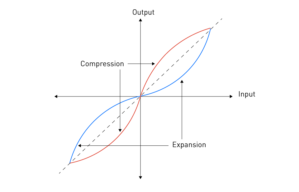
Figure 7: Companding
In some circumstances, the analog signal's amplitude range may be excessively wide or the signal may have a lot of amplitude variation. In such cases, linear encoding might not be the most effective method of signal representation. In these circumstances, companding is a technique used to increase encoding effectiveness.
Compression and expansion are combined in the process of companding. It is a technique for mapping the output code words to the input analog amplitude levels logarithmically. This implies that although bigger amplitudes are encoded more coarsely, smaller signal amplitudes are encoded with greater resolution.

Figure 8: Companding curve
To lessen the negative impacts of quantization noise on low-level signals, standardized companding laws, such as the -law (often used in North America, Japan, and the rest of the world) and the A-law (usually used in Europe and the rest of the world), are frequently employed in telephony systems.
In practical applications, the different steps of the analog-to-digital conversion process must be balanced. To meet the needs of the application, care should be taken in selecting the sample rate, quantization resolution, and encoding approach.
In order to minimize aliasing and make sure that the system only gathers what is required, it is crucial to select an appropriate sample rate. This might help to avoid wasting storage and processing resources.
The desired signal quality should be taken into consideration while choosing the quantization resolution. Lower quantization error is achieved with higher resolution, but at the expense of larger data sets and perhaps slower conversion rates.
The kind of the signal and the application should be taken into consideration when choosing an encoding strategy, such as whether to employ linear or companded encoding.
The system's performance, power use, and cost can all be significantly influenced by the ADC architecture and design decision.
Other crucial factors in system design include noise performance, filtering needs, and error correction methods.